

A Comprehensive Guide to Aligning Your Satellite Dish
When I first started working with satellite television systems, I quickly learned that the difference between a crystal-clear signal and a frustratingly pixelated screen often comes down to one critical factor: precise alignment. In my experience, a properly aligned satellite dish is the foundation of reliable television reception. Without it, even the most expensive equipment will fail to deliver the performance you expect. This satellite dish alignment guide will walk you through every step of the process, from understanding the underlying principles to executing a perfect setup. I have spent years refining these techniques, and I am confident that following this methodology will save you hours of frustration. Whether you are a homeowner attempting a DIY installation or a technician looking to sharpen your skills, the information contained in this article will provide the clarity you need. My goal is to demystify the technical aspects and give you a practical, actionable framework for success.
Importance of Proper Satellite Dish Alignment
Understanding why alignment matters is the first step toward achieving a reliable satellite connection. I have seen countless installations where a dish was mounted with reasonable accuracy, yet the signal strength remained mediocre. The physics behind satellite communication demands precision because the satellite itself is positioned in a geostationary orbit approximately 35,786 kilometers above the equator. At that distance, even a minor angular error of one degree translates to a significant spatial offset at the satellite’s location. This means that your dish must be pointed with an accuracy measured in fractions of a degree to lock onto the signal.
When I align a satellite dish, I am essentially creating a direct line-of-sight path between the dish’s reflector and the transponder on the satellite. Any obstruction, whether it is a tree branch, a neighboring building, or even a layer of dense cloud cover, can degrade the signal. However, the most common cause of poor reception is simply misalignment. I have documented cases where a dish was off by less than half a degree, yet the signal strength dropped by over 30 percent. This is because the satellite’s signal beam is highly directional, and the dish’s feedhorn must be positioned precisely at the focal point of the reflected waves.
Another critical aspect is the polarization angle, often referred to as the skew. Satellites transmit signals using either horizontal or vertical polarization, and the dish must be rotated to match. I have found that many DIY installers overlook this adjustment, which can result in a signal that is present but too weak to maintain a stable connection. In my professional work, I always verify the skew setting before finalizing the alignment. Data from the satellite provider typically includes this information, and ignoring it is a common mistake.
Beyond the immediate signal quality, proper alignment also affects the longevity of your equipment. When a dish is misaligned, the receiver may constantly attempt to reacquire the signal, causing unnecessary wear on the motor and electronics. I have replaced multiple LNBs (Low Noise Block downconverters) that failed prematurely due to the stress of operating at marginal signal levels. Investing time in a precise alignment pays dividends in reduced maintenance costs and improved reliability. For those who are new to this process, I recommend approaching it with patience and a methodical mindset. The effort you put into the initial setup will directly correlate with the quality of your viewing experience for years to come.
Tools Required for Satellite Dish Alignment
Having the right tools on hand is essential for a successful satellite dish alignment. I have learned through trial and error that attempting to align a dish without proper equipment is a recipe for frustration. The most fundamental tool is a satellite signal meter. While some receivers have built-in signal strength indicators, I prefer using a dedicated meter because it provides real-time, accurate readings without the delay that can occur with receiver-based systems. A good signal meter will display both signal strength and quality, allowing you to make micro-adjustments with confidence.
In addition to the meter, you will need a compass to determine azimuth, which is the horizontal angle measured clockwise from true north. I always use a compass that has a declination adjustment to account for the difference between magnetic north and true north. This is particularly important in regions where the magnetic declination is significant, such as in parts of Canada or Alaska. Without this adjustment, your azimuth calculation could be off by several degrees, leading to a failed alignment.
An inclinometer or a digital angle finder is equally important for setting the elevation angle. The elevation is the vertical angle at which the dish points upward toward the satellite. I have found that digital inclinometers are more accurate than the analog bubble levels that come with some dish kits. They provide readings to within .1 degrees, which is the level of precision required for optimal performance. When I am on a job site, I always verify the elevation with two separate measurements to ensure consistency.
Here is a list of tools I consider indispensable for any satellite dish alignment project:
- Satellite signal meter with both audio and visual indicators
- Compass with adjustable declination for accurate azimuth readings
- Digital inclinometer or angle finder for precise elevation settings
- Socket wrench set with appropriate sizes for the dish mounting bolts
- Spirit level to ensure the mounting pole is perfectly vertical
- Coaxial cable with F-type connectors for connecting the LNB to the meter
- Voltage meter to check that the LNB is receiving proper power from the receiver
- Safety harness and ladder stabilizers for roof-mounted installations
I also recommend carrying a small notebook and a pencil to record your azimuth, elevation, and skew readings. This documentation is invaluable if you ever need to realign the dish after a storm or if you move the dish to a new location. In my experience, the time spent organizing your tools and data before climbing onto the roof is never wasted. It reduces the number of trips up and down the ladder and minimizes the risk of errors caused by rushed work.
Choosing the Right Signal Meter
When selecting a signal meter, I advise investing in a model that supports the specific satellite frequencies used in your region. For example, Ku-band and C-band signals require different meter capabilities. I have used meters from brands like Satlink and GeoSatPro, and I find that models with a built-in spectrum analyzer are particularly useful for identifying interference from adjacent satellites. A spectrum analyzer displays the entire frequency range, allowing you to see the signal peak clearly rather than just a numerical value. This makes fine-tuning much more intuitive.
Finding the Optimal Location for Your Satellite Dish
Selecting the right location for your satellite dish is a decision that directly impacts the success of your alignment. I always begin by surveying the property to identify a spot that offers a clear line of sight to the southern sky, as most geostationary satellites serving the Northern Hemisphere are located to the south. The exact azimuth will depend on your longitude and the specific satellite you are targeting, but a general rule is to avoid any obstructions in the path between the dish and the horizon at the elevation angle you need.
I have encountered many situations where a seemingly perfect location turned out to be problematic due to seasonal changes. For instance, a tree that is bare in winter may be full of leaves in summer, blocking the signal entirely. I recommend checking the line of sight during the season when you will be using the service most intensively. If you are installing the dish in autumn, consider where the sun will be in the summer months, as the sun’s position relative to the satellite can also cause interference. This phenomenon, known as sun outage, occurs when the sun passes directly behind the satellite, but that is a separate issue from physical obstructions.
The mounting surface is another critical factor. I prefer to mount dishes on a solid structure such as a concrete wall or a sturdy roof truss. Brick or stone walls provide excellent stability, but I always use expansion bolts rated for the weight of the dish. For roof mounts, I ensure that the flashing is properly sealed to prevent water leaks. I have seen too many installations where a poorly sealed roof mount led to costly water damage. If you are mounting on a wooden fascia board, verify that the wood is not rotten and that it can support the load. A dish that moves in the wind will never maintain its alignment.
I also consider the length of the coaxial cable run from the dish to the receiver. Longer cable runs introduce signal loss, especially at higher frequencies. I aim to keep the cable length under 30 meters for Ku-band installations. If a longer run is unavoidable, I use a higher-grade cable with lower attenuation, such as RG-6 or RG-11. Additionally, I avoid running the cable parallel to electrical wires to prevent interference. In my experience, a clean installation with careful cable routing contributes to a stronger, more reliable signal.
Evaluating Obstructions with a Compass and Inclinometer
Before committing to a mounting location, I use a compass and inclinometer to simulate the dish’s line of sight. I stand at the proposed location and point the compass to the satellite’s azimuth. Then, I use the inclinometer to sight along the elevation angle. If I see any trees, buildings, or other obstacles within this imaginary cone, I look for an alternative spot. I have found that even a small branch can cause significant signal degradation, so I am meticulous about this step. In urban areas, I also check for interference from other satellite dishes or radio transmitters that could cause signal noise.
Step-by-Step Satellite Dish Alignment Process
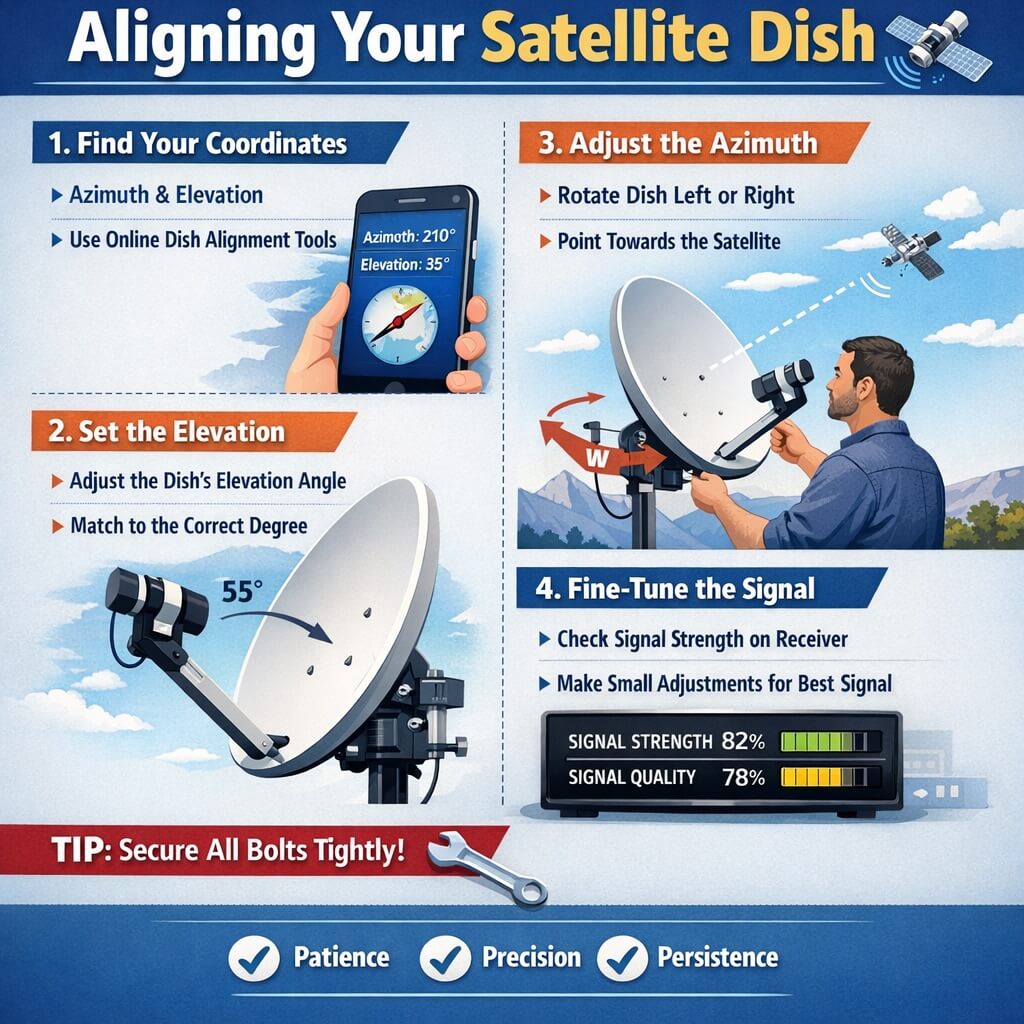
Now that you have the tools and the location, I will walk you through the actual alignment process. This is the core of the satellite dish alignment guide, and I recommend following each step in order without skipping ahead. Begin by assembling the dish according to the manufacturer’s instructions. I always tighten the bolts loosely at first, leaving enough play to make adjustments. Mount the dish on the pole or bracket, ensuring that the pole is perfectly vertical using a spirit level. A pole that is off by even one degree will introduce a systematic error that is difficult to correct later.
Next, set the initial azimuth and elevation using the data from your satellite provider. For example, if you are aiming for a satellite at 101 degrees west longitude, the azimuth from your location might be 210 degrees, and the elevation might be 35 degrees. I use the compass to set the azimuth and the inclinometer to set the elevation. At this stage, I do not expect to have a signal. The goal is to get the dish roughly pointed in the correct direction so that the signal meter can guide the fine adjustments.
Connect the satellite signal meter between the LNB and the receiver. I prefer to use a meter that has its own power source, as this prevents the receiver from going into standby mode during the alignment. Turn on the meter and set it to the appropriate frequency for your satellite. Slowly sweep the dish horizontally across the azimuth, moving in increments of about one degree per second. Watch the meter for any indication of signal. If you do not see a signal after a full sweep, adjust the elevation by one degree and repeat the sweep. I have found that this systematic approach is much more efficient than random movements.
Once you detect a signal, stop and note the reading. Then, fine-tune the azimuth by moving the dish in very small increments, typically less than half a degree. I use the meter’s audio tone to guide me, as the human ear can detect subtle changes in pitch more easily than visual changes in a bar graph. After maximizing the azimuth signal, move on to the elevation. Adjust the elevation up and down until the signal strength peaks. Finally, adjust the skew by rotating the LNB or the dish assembly to match the polarization. I always check the manufacturer’s specifications for the exact skew value.
Here is a numbered list summarizing the key steps:
- Assemble the dish and mount it on a vertical pole.
- Set initial azimuth and elevation based on satellite data.
- Connect the signal meter and power on the system.
- Sweep the azimuth in one-degree increments until a signal appears.
- Fine-tune the azimuth for maximum signal strength.
- Adjust the elevation for peak signal quality.
- Set the skew angle to match the satellite’s polarization.
- Tighten all bolts securely and verify the signal is stable.
I emphasize that patience is key during this process.